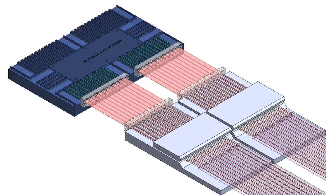
Traditional Approach
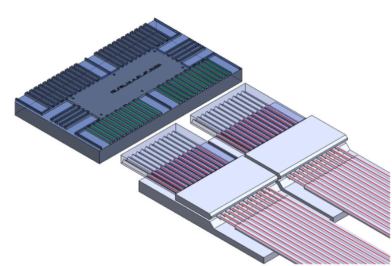
AAYUNA Approach
| Metric | Traditional Collimated (Expanded) Beam Approach | Our Approach |
|---|---|---|
| Performance | ~1.5-1.8 dB additional loss – perfect fiber mode on the PIC to fiber coupling – Accounting for all the components + assembly tolerances | <0.8 dB additional loss – perfect fiber mode on the PIC to fiber coupling – Accounting for all the components + assembly tolerances |
| Cost | 1x | 0.3x |
| System Impact | 3 Interfaces – Laser to PIC + Optical I/O - ~3dB total penalty | Half the number of Lasers (cost/power) or twice the BW |
| Components | FAU + 2 Lens Arrays (Beam expanders) Collimating + Focusing | FAU + Si V-Grooves Bridge |
| Assembly | Very high precision alignment of Lens Arrays on both FAU & WGs on the PIC – CapEx + OpEx (UPH) | Simple – Si V-Grooves Bridge self aligns to the Fibers in the FAU & WGs on the PIC |
| Scalability – No. of Fibers | Assembly complexity increases with the number of Fibers in the FAU | Scales easily with the number Fibers in the FAU |
| Scalability – No. of Units | Due to Equipment cost & Low UPH (due to # of Degrees of Freedom needed for very precise alignment) increases CapEx & OpEx to scale | Due to self alignment of the Lithography defined precise component with standard way of making FAUs, easily scales |